Tuesday, October 25, 2016

Chameleon Softie


I stumbled upon this light colour sensor while trawling around the Internets, and got the idea of using it to build a softie that would change its colour based on what it sensed around it (like a chameleon). This colour sensor uses four different photosensitive sensing elements with different band pass filters for sensing the proportions of red, green, blue and clear (visible?) light. It also has a white LED on board that can be used to illuminate a target surface that sits close to the sensor, in order to provide consistent colour readings under different ambient light conditions. I got the 'Flora' version of the sensor (3.3V only and with sewable pads), but there is also a standard breadboard breakout version of the sensor too which allows for 3.3-5V with the addition of logic level conversion, so it can be used with pretty much any Arduino or other microcontroller. The sensor uses I2C for communication with the micro.

I had a few spare Gemmas sitting around, so I wanted to use this board instead of the larger Flora (of which I had none). A bit of reading here on the Gemma pins and it looks like it's got what I need: I2C comms through pins 0 and 2, which leaves pin 1 for driving some neopixels to light up the chameleon different colours.

I downloaded the library for the colour sensor from here and a library for I2C communication on the ATTiny (micro used on the Gemma and Trinket) from here. I modified the Adafruit_TCS34725 library to use TinyWireM, instead of "Wire" (the built-in Arduino library for I2C communications on larger boards). This pretty much was just replacing every instance in the code of "Wire" with "TinyWireM", a class that provides essentially all the same functionality. I then wrote a sketch that connected to the colour sensor and to four neopixels, and in a loop would read the colour values and basically cut and paste them into the RGB values for the neopixel. The code switches on the illuminating LED on the colour sensor and leaves it on.


Initial result was that I could discern the colours of objects I put in front of the sensor, but the output was very "white", i.e. very low colour saturation values. I wrote a function that would take the RGB values and maximise the colour saturation. I started off by writing a function to first compute the hue from the RGB values, and then produce another set of RGB values of that same hue but at full saturation and value. Unfortunately, I ran out of program space ... the Gemma is super restrictive! I re-wrote the function to do things in one step: set the maximum channel to 255, minimum channel to zero, and intermediate channel scaled between 0 and 255, based on it's relative difference to the max/min values. I just managed to scrape in under the maximum program space (after shaving off a few options in the modified Adafruit_TCS34725 library), but the results were not great: the colour would sort of flick randomly: I think I was saturating the sensor and getting a lot of white signals, which would saturate to random colours.

I ended up going for a simpler solution in which I would subtract a set of calibrated values from each of the RGB channels, to try and get a more saturated output signal. I experimented with several differently coloured objects, including white paper, and tweaked the gains, until I got the desired range of colour replication.


Once I got the electronics working, I turned my attention to building and sewing the chameleon. I wanted to make it entirely out of white felt with the neopixels mounted inside and surrounded by stuffing to diffuse the light out a bit. I experimented a bit to see how close I would need to mount the neopixels from each other and how much stuffing to use to try and get the illumination from the neopixels spread out as evenly as possible. Once I had this sorted I cutout and section of felt and sewed up the Gemma and neopixels circuit using conductive thread. I designed the Gemma to sit on one eye of the chameleon, and the colour sensor on the other, such that the Gemma was accessible for turning on/off. I then designed the chameleon's outside body, cut it out of felt, and sewed it together with the nexopixel circuit. Once completed, I sewed on the colour sensor to the other eye and sewed all the conductive lines to the Gemma. I stuffed the insides with soft fill in order to puff out the chameleon and diffuse some of the light from the neopixels, such that it would look like the chameleon was sort of glowing.


The end result was OK. I had to fiddle around a lot with the calibration gains on the colour channels to get good matching for various colours. I was a bit disappointed I couldn't add more functionality to the programming ... I would have liked to have a bit more intelligence in inferring when the chameleon was moving or still, so I could decide to actively flash the white LED and get another reading, otherwise if still, just leave it off. One of the limitations of the ATTiny85 on the Gemma ... still, it's cool that its so small.

The code for the sketch is available here.

Friday, October 14, 2016

Rolling Ball Maze on Carvey


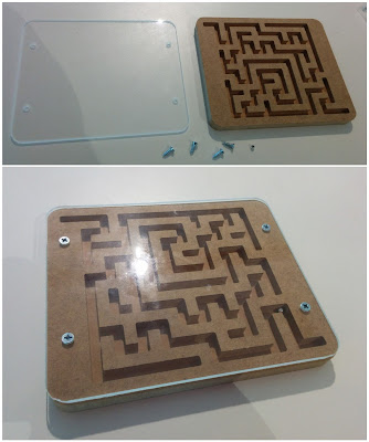
My local maker space, Thinkspace, has had a Carvey for a couple of months, and I've finally gotten around to giving it a try. I decided to make a little rolling ball maze by using Carvey to carve a 3D maze path into a piece of wood and cover it from the top using some clear acrylic.

I found some python code here for randomly generating orthogonal mazes using a simple random depth first search algorithm. I modified to code to take the resulting maze and calculate the set of 2D line segments corresponding to the inner space of the maze (what I would be carving). I then added code in the python script to output the set of lines at an SVG vector graphics file that could be read into the Carvey software Easel. SVG line segments in Easel/Carvey get treated as a single pass by the carving bit, and hence the line thickness is dictated by the thickness of the drill bit used. The largest milling bit available was 1/8 inch, and so the path of the maze was pretty narrow. I went ahead and tried it out anyway, just to see that it worked.

In order to provide mazes with a larger channel width, I tweaked my python script to also output SVG files in which each line segment was represented by a rectangle object. I tried carving a maze with a 1/4 inch channel thickness using a 1/8 inch milling bit, and results still looked good. I found some information here that explained that Easel assumes the coordinates in the SVG file during import correspond to 96 pixels per inch, and hence I scaled my maze coordinates accordingly to make the distance between channels twice the milling bit diameter, such that the maze channels and walls were equally thick.


For the finished product I added a cut out around the maze with rounded edges. I also created a second piece carved out of clear acrylic to cover the maze so that the ball doesn't fall out. For the acrylic cover, I also added four holes so that I could screw on the cover to the wood. I wanted the screws to sit flush with the acrylic surface, so each hole has one diameter that goes straight through the material and a second larger diameter hole that just goes 2 mm in, and acts as a countersunk hole. Once Carvey had finished milling out the two pieces, I placed a little silver bead inside the maze and screwed the cover on top with four screws. I also used a hand drill to put in some pilot holes for the screws: I was going to do this with Carvey, but I was using a 1/8 inch milling bit and my screw threads were smaller than this.

You can get the python script to generate your own maze including acrylic cover here: generate_carvey_ballmaze.py. Import the generated SVG files one at a time into Easel. These files assume a 1/2 inch thick piece of material for the maze and a 3 mm thick acrylic with 1/4 inch diameter screws.

Wednesday, October 12, 2016

Electric Piano Part 1: Turning an old piano into a simple synth and MIDI device


Recently, my father in law donated an old electronic piano keyboard for me and my son to play around with, an old Yamaha PSR 8 from the 1990s. When we brought it home, my son accidentally pulled off the tip of the 9V DC adaptor that came with it and when I plugged it back on I got the polarity wrong and we broke it (sad face). Yah, I know, I know ... I got lazy and thought I definitely had it the right way (who knew there was no standard for the polarity of DC power pack tips? Now I do) ... will always check with the multimeter from now on.

So I opened up the case and had a peak around. Can't see any obvious physical damage (no burnt out or broken components). Had a search online for some repair manuals for this keyboard and found a few pages, but to be honest wasn't that keen on trying to find replacements parts. So ... only one thing left to do: gut it and rebuild the electronics again from scratch!


I unscrewed and pulled away the actual keyboard assembly from the rest of the case. Had a look at the keyboard itself and contacts for keys. Running along the back of the keys is a single long PCB with contacts for each key and a bunch of diodes on it (one for each of the 49 keys) that all map back to a 15 pin connector. A bit of googling and it looks like this is a switch matrix. I found this helpful reference which seems to explain how this circuit works: keys are grouped into nine rows, each with a set of six keys (except for the last row which contains a single key), where each key in a row shares a common ground, and the first pin of each row shares a common contact on the other end of a diode, as does all the second pins etc. The state of each of the 49 keys can be read by selectively reading from 6 digital input pins while incrementally setting 9 output pins to ground one at a time.


I decided to use my Teensy 3.2, which I hadn't previously used, to do the reading of keyboard state. I installed the teensyduino add on for Arduino 1.6.11, tested out an LED blink code and got a 4 ohm speaker working with simple melody. I then got a simple, single switch working with a INPUT_PULLUP mode, all good, lighting up pin 13 LED. Then I wrote a sketch to flick back and forward between two pins, both in INPUT_PULLUP mode and to a common ground, by setting the other pin OUTPUT/HIGH while reading the other (diodes built into the keyboard to stop current pulling between pins when both keys are down). Working well.


I snipped and stripped the ribbon cable I found connected to the 15 pin connector coming off the key switch PCB, plugged it into my breadboard and connected to 15 digital pins on the Teensy. I wrote a sketch to implement a basic matrix to read out all 49 keys. I found I had to add in a 10 us delay between setting Teensy pins to INPUT_PULLUP mode and reading them (as suggested by the Teensy instructions on their website) and also found I had to add a 50us delay between subsequent reads of each key on the matrix to get things to work such that more than one key could be read at a time. Once all keys read, wrote a program to output the tone corresponding to the highest key. Basic monophonic piano implemented!

I decided to round off this design my modifying the Teensy built in tone function to produce four simultaneous tones using the 4 PIT timers available. I modified the standard Teensy tone implementation to use up to four timers simultaneously and prioritised timers to the higher keys on the piano. I used four pins each connected through a 330 ohm resistor back to the speaker and I also chucked on a potentiometer for volume control. Working fine, and I could now play polyphonic tunes pretty well (up to four simultaneous key presses). The square waves sounded pretty ordinary through the little 4 ohm/500mW speaker, so I also tried connecting the ends to an RCA co-axial cable and plugging it into an external amplifier, which was a little better.

The code for running this all can be found at:
https://github.com/mit-mit-randomprojectlab/keyboard_multitone

At this point I decided to try an alternative direction for the design: instead of doing the sound synthesis on the Teensy, what if I used an additional computer or micro to do it for me? I decided to try and get the keyboard working as a MIDI device. I changed the code to output MIDI "noteon" and "noteoff" messages on key presses and configured the teensy to output MIDI, using the options available in the Arduino IDE. The teensy library in teensyduino makes this very easy: there are a bunch of send/receive midi functions built in, no need for any additional code or external libraries.

The code for running this all can be found at:
https://github.com/mit-mit-randomprojectlab/keyboard_midi001

Once i got the keyboard working as a MIDI device, I downloaded and installed "Fluidsynth" on my macbook to read in the MIDI messages and play sounds. I used the "General User GS v1.47" font by S. Christian Collins and started up Fluidsynth from the command line using the following settings: ./fluidsynth GeneralUser_GS_v1.47.sf2  -o midi.driver="coremidi" -o audio.driver="coreaudio"
I then used a software package called "MIDI Patchbay" to patch the output from the Teensy to Fluidsynth, and voila! I can play synthesised piano through my laptop. Once in fluidsynth, I used "prog <channel> <inst>" to set different instruments.

So thus far I've managed to (a) make a simple synth (square waves) which is OK, but lets face it, my son will only find squares waves interesting for a short amount of time! and (b) make a MIDI keyboard, which can play all sorts of cool sounds, but only when connected to and setup on my laptop, so my son can't really go and turn it on and play himself. I am going to try and keep going down both design routes and (a) get a synth working on the teensy that can play a wider variety of tones/waveforms and (b) try connecting the MIDI keyboard up to a dedicated raspberry pi for doing the audio synthesis. Stay tuned!