Tuesday, December 24, 2019

Arduino-powered Gingerbread House

This year for Christmas, my wife made each of us in our family a gingerbread house to decorate during the holidays: a great activity to do together and break up the otherwise endless cycle of eating and video games :). We decided to make a theme that we would all decorate to: "bright and colourful", fairly straight forward. I couldn't help myself and so I wanted to integrate in some electronics and colourful lights to really add to the brightness factor!

I put a spare Circuit Playground I had sitting around to good use, by programming a little rainbow light show to go with my house: the light show is activated by a digital microphone on the board by blowing gently into the window of the house. I would have had a Christmas tune playing on the board too, but unfortunately the speaker on my Circuit Playground isn't working.

The Arduino sketch can be found here:

https://github.com/mit-mit-randomprojectlab/gingerbreadhouse_lights

Merry Christmas!

Sunday, December 15, 2019

Arduino Power Moon


It's that time of year again so time for a Christmassy sort of project to round out the year. In the past I've 3D printed lots of Christmas decorations, so I thought it was time to make a nice Christmas tree topper. Normally this would be a star, but my son has been playing lots of Super Mario Odyssey lately, and I wanted to make something he would think was cool, so I went with a Mario-style Power Moon from the game.


I wanted to add a bit of light and sound, so I started digging through spare Arduino boards to see what I could make work with battery power in a minimal footprint. I ended up using a Adafruit Gemma m0, as it's small, has a battery JST input, on/off switch and a single Dotstar three-colour LED mounted on the board already. All I needed to fit in with it was a small lipo battery and 8ohm speaker for sound and it was good to go.


I wanted the power moon to be able to change colours (as they appear in various colours in the game, depending on which kingdom you are in), so I 3D printed the moon using transparent filament and designed a little cavity inside the moon to house the electronics and light. The resulting effect with the LED on is that the filament catches the light and creates a nice glowing effect.

For music, I wanted to go just a little step beyond a series of single tone beeps, so I did a little research on how to get timer counters and interrupts going on the Gemma m0 (and other SAMD boards), mainly by studying the existing Arduino "tone" implementation for this chip. I ended up creating a modified set of tone functions that use both timer 4 and 5 to generate two pulse wave voices so I could play some very basic polyphonic music. There are three I/O pins on the Gemma and I wanted to keep one free as a switch to control the activation of lights and sound, hence just two sound channels.

For the electronics, I soldered the Gemma pins directly to each end of the speaker (via a pair of resistors) and wired up a vibration-activated switch between one of the digital inputs and ground, so that I could trigger light/sounds shows without having to put in a button, or open up the case. I fit a small lipo battery in between the Gemma and the speaker, so everything is together in a small disc-shaped package.

For music, I composed some two part tunes using Musescore and wrote a little python script to convert Musescore mscx files (XML formatted files that contain the music data in terms of the note pitches, timing and durations) into data embedded into a header file I could compile straight into the Arduino code. I then wrote a system in for pulling out the appropriate note data at the appropriate time to pass on to the modified tone code.


The moon is made up of two halves that need to be able to come apart (in order to switch it on/off and take the battery out for re-charging), so in order to have something that can open and close easy, I glued some small magnets to the inside of each side of the case that hold the moon together. Seems to work pretty well!

Here's a video of the moon in action: Merry Christmas!


Design Files:

3D Printed Case STL files:
https://www.thingiverse.com/thing:4047914

Code for running the power moon:
https://github.com/mit-mit-randomprojectlab/power_moon

Saturday, August 3, 2019

Mini Electronic Connect4 Game

I've just finished a new electronics project: it's a mini electronic connect4 game, with a built-in computer opponent. It runs on an Adafruit M0 Featherboard and uses an bi-colour 8x8 LED matrix display as the gameboard. There are three buttons for controlling the player's moves in the game. The device has a 3D printed case, is portable, battery powered and USB-rechargeable (via the featherboard). The game functionality is programmed in Arduino and features an AI opponent, with a moderate level of difficulty.

I had the matrix display sitting around for a while, and I had been trying to think of a cool project to use it for. When a group of colleagues at work started up a connect4 python bot programming challenge, I got inspired to try and implement a bot into the lower-powered processing capabilities of a smaller micro-processor, so I thought this would be a great use for the display. I started off by testing out the display: I soldered on the backpack to the LED matrix and wires onto the power, ground and I2C lines on the backpack so I could connect it to a breadboard. I hadn't soldered on the headers for my featherboard M0, and I had a Gemma M0 sitting around so I connected it up to the backpack using some jumper leads and alligator clips to test it. I used the 3.3V output from the Gemma: seems to drive the matrix with no problems. I downloaded the Adafruit libraries to drive the LED backpack and the Adafruit GFX library, which provides some basic functionality for drawing primitive geometry and rendering text to the display: I ran one of the example scripts for the backpack and all was working well.


I started developing the code for a connect4 game and an AI to play against. The AI uses a Monte Carlo Tree Search algorithm for evaluating the next best move based on simulating games to approximate win/loss statistics. This seemed like the quickest and easiest approach to develop, seemed to require less memory that a Minimax approach, and I'm assuming provides a little bit of random variation in the AI's play, such that games against a human would be a bit more interesting.

Played around a bit with the AI to try and get it to prioritise early wins/avoiding early losses: cost for loss = 42-n_moves, cost for win = 42-n_moves, then score = win_cost - loss_cost: works OK, but doesn't correctly prioritise avoiding when the player will definitely win on the next turn: so I had to hard code a few initial checks in so the AI first looks for instant win moves, then for moves which block the player winning on the next move, then Monte Carlo.


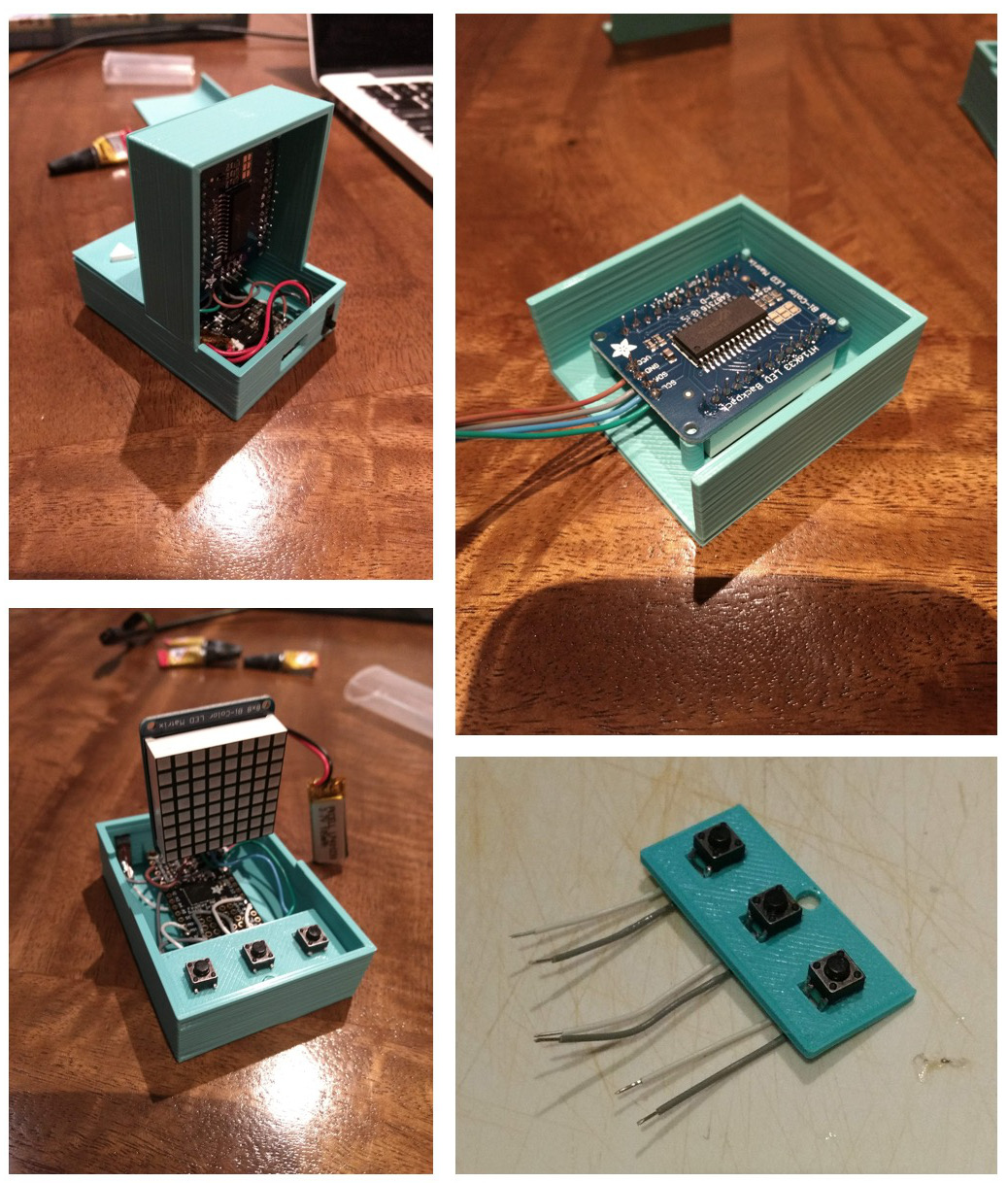
Once I was happy with the code, I started working on the design of the physical device and casing. I started off with the idea of having a custom-built rotary input wheel on the top of the game that would allow the player to turn the wheel to move the location of the piece to drop, then click the wheel to drop the piece. I bought some mini trimpots to use as input with custom-designed 3D printed cog to interface with trimpot. After experimenting with a couple of 3D prints for the knob, I ended up dropping this idea as the trimpots I could find all had so much friction, that they were almost impossible to turn using a single finger without having to have a giant sized knob to achieve the appropriate torque. I ended up instead going with a more traditional arcade button layout with one button to move the cursor position left, one right and a third button to place the token.


I designed the 3D printed case to look a little bit like a connect4 board, except that it's quite fat, which is needed to fit everything inside (particularly the matrix display, which is quite thick when the breakout board is soldered on). It printed from multiple sections that are then glued together.


For the electronics, I began by laying out in the case where the components would fit and how I would wire everything together. The case is quite small, so I had to plan out the layout of wires to ensure it did't get too messy on the inside. I wired all the electronics together first, separate from the case, and tested everything was working, before moving on to connecting and gluing on the case.

The tabs I had designed to hold the micro to the case turned out to be a touch too big for the mounting holes on the board, so ended up having to snap them off and superglue the board to the case. The other sections of the case all fit together nicely, and I ended up using superglue to connect all the separate sections of the case together. The final product is fairly neat looking and compact: it even does look a little bit like a mini connect4 board!

I really enjoyed working on this project: it was fun to design a case that had a couple if different sections and was a little less "flat" than some of the previous 3D printed electronics projects I've worked on before.

Design Files:

3D Printed Case STL and OpenSCAD files:
https://www.thingiverse.com/thing:3785812

Code for game control and AI:
https://github.com/mit-mit-randomprojectlab/arduino_connect4


Friday, April 26, 2019

PyWeek 27: Breakout Blue


"Breakout Blue" was our (Team Chimera) team entry for PyWeek 27 (April 2019), a twice yearly video game development competition that gets competitors to build a complete game from scratch in seven days using the python programming language. This competition's theme was "six", and we made a game in which you control six inmates trying to work together to perform a prison escape.


I teamed up with Lucid Design Art, the other half of Team Chimera: it was our first collaboration in about two years, and it went well. I worked on game programming, music and sound, and Lucid worked on game design and artwork. The game involved a combination of puzzle elements and a little bit of stealth, and turned out well. We placed second in the team entries and tied for second overall with a score of 4.13/5.0 so we were pretty pleased with the result.


Playthrough Video:


You can download and play the game from source (requires python (2 or 3) and pygame installed).

Saturday, March 16, 2019

3D Cube Rolling Ball Maze on Carvey

A while ago I made a rolling ball maze on Carvey, a soft-CNC machine at my local maker space. For a bit of extra fun, I've extended this now into the third dimension and created a cube-based rolling ball maze. The maze has six sides that are all inter-connected and makes for a bit more of a challenging experience. The cube maze is pretty much the same concept as a bunch of cheap plastic cube mazes you can but on Amazon etc. but a little bit bigger. To generate the actual maze itself, I developed a random maze generator in python using a recursive backtracking algorithm. I extended the approach to build the maze across the surface of a cube by placing maze nodes in a regular grid across each of the six faces of a cube and placing a number of random edges between adjacent face nodes to create paths that traverse the whole grid surface. The scripts I made output the generated maze as an image showing an "unfolded" view of the cube, and also spit out SVG files for carving.


The maze is carved as six separate sections from 9mm MDF and six 2mm thick clear acrylic panels (to stop the ball falling out). The panels are then glued and screwed together by hand. I had a look into a couple of different options for the track size of the maze. I have a few 2mm steel ball-bearing balls, but found that these don't actually work well: they are so small that roll too quickly in the maze and it becomes very frustrating to move them around by tilting the maze. I ended up using a silver coloured decorative ball for cake decorating: turned out to have the right size (approx. 4mm diameter) and rolls quite nicely.


Putting it all together was a little bit finicky: seeing as Carvey can only cut in 2.5 dimensions (three axis carving) I had to design the pieces to be of varying sizes such that they all interlock together and allow for the tracks to join up. The little bits of wood at the bottom were glued in as a way to chock the two smallest panels up against the clear panelling so the whole thing stays together.


Design files for the maze I ended up using (as SVG files that can be used for Carvey/Easel) can be downloaded here:


Python scripts for generating new random mazes and associated design files available via Github: