It's that time of year again so time for a Christmassy sort of project to round out the year. In the past I've 3D printed lots of Christmas decorations, so I thought it was time to make a nice Christmas tree topper. Normally this would be a star, but my son has been playing lots of Super Mario Odyssey lately, and I wanted to make something he would think was cool, so I went with a Mario-style Power Moon from the game.
I wanted to add a bit of light and sound, so I started digging through spare Arduino boards to see what I could make work with battery power in a minimal footprint. I ended up using a Adafruit Gemma m0, as it's small, has a battery JST input, on/off switch and a single Dotstar three-colour LED mounted on the board already. All I needed to fit in with it was a small lipo battery and 8ohm speaker for sound and it was good to go.
I wanted the power moon to be able to change colours (as they appear in various colours in the game, depending on which kingdom you are in), so I 3D printed the moon using transparent filament and designed a little cavity inside the moon to house the electronics and light. The resulting effect with the LED on is that the filament catches the light and creates a nice glowing effect.
For music, I wanted to go just a little step beyond a series of single tone beeps, so I did a little research on how to get timer counters and interrupts going on the Gemma m0 (and other SAMD boards), mainly by studying the existing Arduino "tone" implementation for this chip. I ended up creating a modified set of tone functions that use both timer 4 and 5 to generate two pulse wave voices so I could play some very basic polyphonic music. There are three I/O pins on the Gemma and I wanted to keep one free as a switch to control the activation of lights and sound, hence just two sound channels.
For the electronics, I soldered the Gemma pins directly to each end of the speaker (via a pair of resistors) and wired up a vibration-activated switch between one of the digital inputs and ground, so that I could trigger light/sounds shows without having to put in a button, or open up the case. I fit a small lipo battery in between the Gemma and the speaker, so everything is together in a small disc-shaped package.
For music, I composed some two part tunes using Musescore and wrote a little python script to convert Musescore mscx files (XML formatted files that contain the music data in terms of the note pitches, timing and durations) into data embedded into a header file I could compile straight into the Arduino code. I then wrote a system in for pulling out the appropriate note data at the appropriate time to pass on to the modified tone code.
The moon is made up of two halves that need to be able to come apart (in order to switch it on/off and take the battery out for re-charging), so in order to have something that can open and close easy, I glued some small magnets to the inside of each side of the case that hold the moon together. Seems to work pretty well!
Here's a video of the moon in action: Merry Christmas!
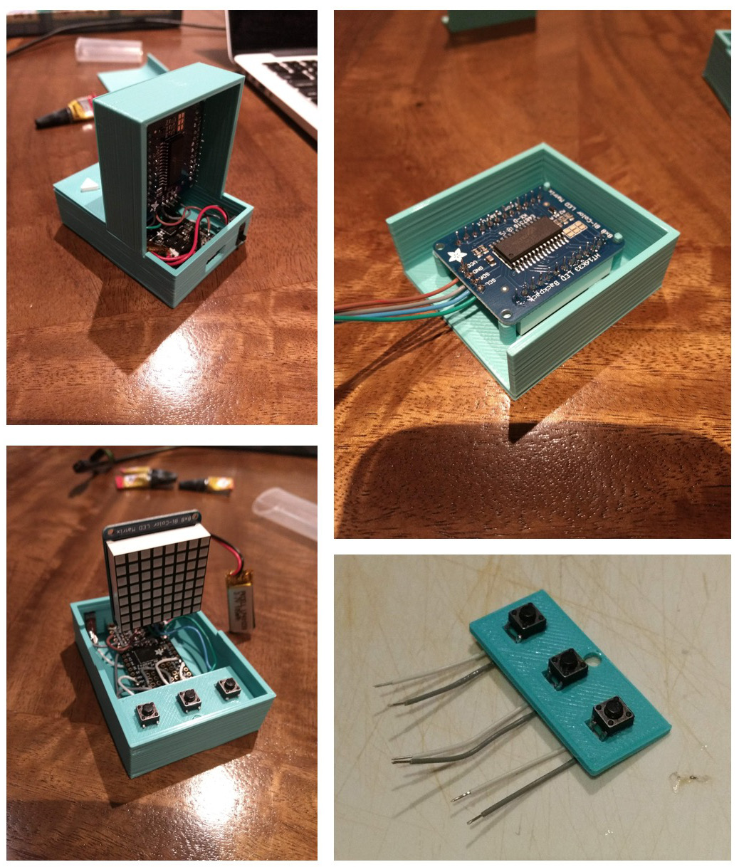
I've just finished a new electronics project: it's a mini electronic connect4 game, with a built-in computer opponent. It runs on an Adafruit M0 Featherboard and uses an bi-colour 8x8 LED matrix display as the gameboard. There are three buttons for controlling the player's moves in the game. The device has a 3D printed case, is portable, battery powered and USB-rechargeable (via the featherboard). The game functionality is programmed in Arduino and features an AI opponent, with a moderate level of difficulty.
I had the matrix display sitting around for a while, and I had been trying to think of a cool project to use it for. When a group of colleagues at work started up a connect4 python bot programming challenge, I got inspired to try and implement a bot into the lower-powered processing capabilities of a smaller micro-processor, so I thought this would be a great use for the display. I started off by testing out the display: I soldered on the backpack to the LED matrix and wires onto the power, ground and I2C lines on the backpack so I could connect it to a breadboard. I hadn't soldered on the headers for my featherboard M0, and I had a Gemma M0 sitting around so I connected it up to the backpack using some jumper leads and alligator clips to test it. I used the 3.3V output from the Gemma: seems to drive the matrix with no problems. I downloaded the Adafruit libraries to drive the LED backpack and the Adafruit GFX library, which provides some basic functionality for drawing primitive geometry and rendering text to the display: I ran one of the example scripts for the backpack and all was working well.
I started developing the code for a connect4 game and an AI to play against. The AI uses a Monte Carlo Tree Search algorithm for evaluating the next best move based on simulating games to approximate win/loss statistics. This seemed like the quickest and easiest approach to develop, seemed to require less memory that a Minimax approach, and I'm assuming provides a little bit of random variation in the AI's play, such that games against a human would be a bit more interesting.
Played around a bit with the AI to try and get it to prioritise early wins/avoiding early losses: cost for loss = 42-n_moves, cost for win = 42-n_moves, then score = win_cost - loss_cost: works OK, but doesn't correctly prioritise avoiding when the player will definitely win on the next turn: so I had to hard code a few initial checks in so the AI first looks for instant win moves, then for moves which block the player winning on the next move, then Monte Carlo.
Once I was happy with the code, I started working on the design of the physical device and casing. I started off with the idea of having a custom-built rotary input wheel on the top of the game that would allow the player to turn the wheel to move the location of the piece to drop, then click the wheel to drop the piece. I bought some mini trimpots to use as input with custom-designed 3D printed cog to interface with trimpot. After experimenting with a couple of 3D prints for the knob, I ended up dropping this idea as the trimpots I could find all had so much friction, that they were almost impossible to turn using a single finger without having to have a giant sized knob to achieve the appropriate torque. I ended up instead going with a more traditional arcade button layout with one button to move the cursor position left, one right and a third button to place the token.
I designed the 3D printed case to look a little bit like a connect4 board, except that it's quite fat, which is needed to fit everything inside (particularly the matrix display, which is quite thick when the breakout board is soldered on). It printed from multiple sections that are then glued together.
For the electronics, I began by laying out in the case where the components would fit and how I would wire everything together. The case is quite small, so I had to plan out the layout of wires to ensure it did't get too messy on the inside. I wired all the electronics together first, separate from the case, and tested everything was working, before moving on to connecting and gluing on the case.
The tabs I had designed to hold the micro to the case turned out to be a touch too big for the mounting holes on the board, so ended up having to snap them off and superglue the board to the case. The other sections of the case all fit together nicely, and I ended up using superglue to connect all the separate sections of the case together. The final product is fairly neat looking and compact: it even does look a little bit like a mini connect4 board!
I really enjoyed working on this project: it was fun to design a case that had a couple if different sections and was a little less "flat" than some of the previous 3D printed electronics projects I've worked on before.
Made a few more Nintendo-themed 3D printed Christmas decorations, to add to my existing ones. These are a bunch of power-ups form Super Mario Bros. 3 on the NES. Using a python script to read in an image file and convert into ASCII code for OpenSCAD, then importing this into an OpenSCAD file to generate the stl files for each of the five colour layers, each printed separately and then "clicked-in" by hand to finish.
This is part two (see part one) of a post on a custom-built Arduino-based synthesizer and keyboard called “Pentasynth”. Pentasynth uses a keyboard based on a five note pentatonic scale, so it’s easy to play for people with limited background in music (such as young kids) and encourages experimentation and improvisation. Pentasynth creates a user-selectable accompaniment including different drum patterns, bass lines and chord progressions and allows the user to play a pentatonic melody line over the top. Under the hood, Pentasynth runs on an Adafruit Metro Mini (using the same ATmega328 microcontroller as the Arduino Uno) and generates three channel audio (two square-wave tones and one pseudo-random noise drum beat), which is passed through and onboard amplifier and speaker, while simultaneously passing all outputs as MIDI messages via the USB for either a lo-fi or hi-fi audio experience. Pentasynth has controls for volume, tempo and selection of different accompaniment patterns. The keys and case components are 3D printed, with the main case panelling carved from clear acrylic using Carvey. Custom PCBs containing switches for detection of key presses were also carved on Carvey.
In the previous post, I discussed the hardware development of the keyboard including 3D printed keys and CNCed case and key switch PCBs, and the use of a wavetable synth for audio. I wasn't that happy with the audio quality from the wavetable synth, so I re-wrote my own system using hardware PWM square-waves for audio, with a bit of re-jigging to add MIDI output. I'll also discuss the electronics in a bit more details and the code running on the Arduino.
The ATmega328 has three hardware timers that can each be used to drive interrupt routines or run a hardware Pulse Width Modulation (PWM) signal. Since I wanted to keep the main program on the microcontroller free to managing key and control inputs and running an accompaniment system, the hardware timers were the only way to generate audio signals. By default, two of these timers (Timer 1 and 2) are unused, and the other (Timer 0) is set to run at 1kHz and controls functions such as millis() and delay(): any change in this frequency would mess with these. I've setup Timer 2 to run a square-wave output based on the note pressed on the keyboard and Timer 1 to run a square-wave from an accompaniment baseline. In order to get a pseudo random noise signal for a drum beat, I've piggy-backed an interrupt routine on the existing 1kHz to generate a pseudo random square-wave (i.e. randomly ordered series of LOW/HIGH) using a Galois linear feedback shift register (see this nifty little post). The random signal switched at 1kHz sounds a bit like a snare or open high-hat, so makes for a decent (lo-fi) beat.
I ended up re-jigging the electronics to account for the changes in signal generation (I'm glad now I had left everything breadboarded on the final keyboard :) ). The three audio channels are generated as separate square-waves on three digital output lines (pins 9 and 11 on the metro mini, corresponding to the hardware PWM outputs) and pin 13 for the drum beat. The separate signals are then all connected together via 220 Ohm resistors to a potentiometer pin used for volume control. This output is then fed through a single NPN transistor, which is also connected the the 5V output, acting as an amplifier which is then connected to a 3W, 4 Ohm speaker. The ten keys and four control buttons are connected to the remaining digital input pins, and a second potentiometer connected to an analog input pin which is used as tempo control for the accompaniment.
In terms of code, the microcontroller polls the switches corresponding to each key and send the appropriate tone via both the audio output (hardware PWM) and a MIDI message. The code also implements an accompaniment system. This consists of a drum beat, base line pattern and four-step chord progression that runs along at the user selected tempo. The control button for each of the drums/bass/chord is used to cycle through the available patterns: the player can therefore experiment and choose a combination of drums, bass pattern and chord progression that they like and then improvise a melody over the top of this using the keys. A fourth control panel button is used to switch between different pentatonic modes (at this stage either a major or minor pentatonic scale).
The video shows the keyboard in action. My five year old son has been having fun playing around on it: I think he mostly likes that he can ramp the tempo up to crazy speed and mash the chord progression button to create havoc :).
I’ve been working on another music project: it’s a custom-built Arduino-based synthesizer and keyboard called “Pentasynth”. Pentasynth uses a keyboard based on a five note pentatonic scale, so it’s easy to play for people with limited background in music (such as young kids) and encourages experimentation and improvisation. Pentasynth creates a user-selectable accompaniment including different drum patterns, bass lines and chord progressions and allows the user to play a pentatonic melody line over the top. Under the hood, the audio generation is performed using a four channel, 10kHz playback of wavetables (sine, pulse, sawtooth, triangle and random noise) using a micro-controller generated PWM that is then passed through a low-pass filter and into a small amplifier and speaker. The microcontroller is programmed in Arduino, with code based on “The Synth”, a wavetable synth library by DZL/Illustron. Pentasynth has controls for volume, tempo and selection of different accompaniment patterns. The keys and case components are 3D printed, with the main case panelling carved from clear acrylic using Carvey. Custom PCBs containing switches for detection of key presses were also carved on Carvey.
My local makerspace (Thinkspace) got in some carvable PCB blanks for Carvey last year, and I had been thinking about trying them out. A while ago, I had picked up a broken kids toy electric guitar from the side of the road (I like picking up random electronics junk I find :) ). I ripped it apart just out of curiosity to see how it worked. The guitar was controlled by little buttons: the buttons were basically bits of plastic that held a little piece of clear rubber with a little bit of conductive material in it. When the button is pressed, it would push the conductive material across a PCB with a criss-cross of conductive tracks that close a switch, that is then detected by a little microcontroller to produce a sound:
I salvaged out the little clear rubber bits and decided to try and carve my own PCB “criss-crosses” for the keys on my own keyboard. The advantage of designing it this way, instead of using some off-the-shelf buttons (the usual “clicky” kind) is that the keys then have a nice, soft tactile feel to them and don’t make a horrible “clicky” sound, that interferes with the music (I had regretted using clicky switches in a previous handheld video game project I made).
For carving the PCBs, I used these 2-by-3 inch PCB blanks and designed the circuit as an SVG with paths to cut out the ground and positive voltage paths for each of the ten switches (ten keyboard keys). I had to split the pads across three separate PCBs. I used a V-shaped milling bit (20 degrees) to mill the cuts into the PCB at a cutting depth of approximately 0.2mm. I found that in practice the height wasn't super accurate on Carvey, so had to experiment with different height each and every time I setup a new board to mill. Once the tracks were milled, I used a 1/16in to drill holes for screws and through holes for soldering connections to the PCB pads, and a 1/8in flat milling bit to cut out the final board.
I 3D printed banks of keys in different colours: I designed the “neck” of each key to be a 1mm height layer which produced the flex that allowed the key to swivel when pressed (printed in PLA). The keys were coloured in lots of three and two per octave, to give the feeling of the black keys on a normal piano (which also follow a major pentatonic scale). Originally I intended to design the entire case as a single 3D print, but found it was going to be fairly big (and hence take forever to print), so I ended up changing the design. I created one big baseplate out of clear acrylic (which I carved on carvey, with drill holes) and connected everything to this with screws and a screwdriver. I 3D printed an array of standoffs and other knick knacks to hold the assembly together. I also carved from clear acrylic a top panel which held two dials (one for volume, one for accompaniment tempo) and four control buttons for the accompaniment. This panel also had the small speaker mounted to it.
For the electronics, I used a Adafruit Metro Mini 328 (running at 5V/16MHz), an Arduino compatible board that uses the same ATmega328 chip as the Ardunio Uno. Each of the ten keys is connected to separate digital-in pins, and the remaining GPIO pins are connected to buttons and pots for the controls. The digital PWM output from the micro is then connected to an RC/low-pass filter (to create the waveforms from the PWM pulses) and the output sent to a 4-ohm, 3W speaker after amplification. Originally I had a small D-class audio amplifier I had left over from another project, but I accidentally broke it while desoldering an existing header off it, and so had to put together a simple, single stage transistor amp (which is very soft, and a temporary fix until I get another amp).
Instead of hard-soldering everything into the arduino, I got a bit lazy and decided to glue a small breadboard in and connect everything up via the breadboard. The advantage with this is that I can plug and swap-in a different microcontroller/synths/amplifiers in the future (which I am intending to do).
I'm pretty happy with the look and feel of the keyboard (it's a bit raw looking, but kind of cool), but not super happy with the sound at the moment: I need to get a proper amp for a bit of amplification, and I've found that the audio from the arduino synth library I'm using is not super nice sounding (it sounds a bit like a bad/cheap kids toy piano at the moment). I'm going to do some brainstorming for updating the audio, hence a probable part two post on the project: stay tuned!
The 3D models of printed parts and carvey SVG design files can be found here:
With Global Game Jam 2018 coming up soon, I had the idea of building an alternative video game controller for which I could design a game for during the jam. I recently got my hands on an Adafruit Bluefruit LE m0 Featherboard, an Arduino-compatible microcontroller with built-in low-energy bluetooth module and I was quite keen to try and find a project to test it out on. I started thinking of types of control mechanisms that you don't really find on modern, conventional game controllers: I didn't really have too much time to try and use something really exotic that I'd have to order in, so I ended up thinking about paddles. Old games controllers dating back to the 1970's commonly used a single paddle, or rotational knob, for example on the Magnavox Odyssey and the Atari 2600. The original arcade version of Pong, one of the first video games used two potentiometer knob controllers for two player controller of in-game "paddles" (hence the origin of the term, in relation to the on-screen object the players control). No modern game controllers seem to use paddles or knobs anymore. I had a bunch of spare potentiometers sitting around, so I decided that I'd base the controller around a group of these rotational inputs.
I started off by testing out the bluefruit featherboard; I soldered on the headers, downloaded the appropriate packages for this board for use with the Arduino IDE. Connected it up and got the blink sketch working. I downloaded the Arduino bluefruit library and uploaded and ran the "controller" sketch from the examples that came with the library. I then installed the Adafruit Bluefruit LE Connect app on my android phone and connected to the featherboard. Messages all appearing normally on the serial console when selecting colours in the app. I then modified this sketch to colour a Neopixel based on the colour received through the colour picker function. I connected a neopixel up to PIN 5 and everything working well. I also downloaded the Adafruit BLE desktop app for OSX and tested the connection was working smoothly between the featherboard and my laptop, all good.
I found this library for interfacing on the desktop end via python. I tested the provided example 'list_uarts.py'; was working correctly to find the featherboard when it was switched on. I used this code as the basis for integrating communications with the bluetooth module in a pygame loop. I had to embed all of the code to connect to the device and continuously poll data into a separate thread which was called from a Scene/Director class and dumps the latest polled controller data into variables that gets read by the game during an event call. Everything seemed to work ok; perhaps a little bit laggy (approx. 100-200 ms of lag), but it's hard to tell.
I started designing a 3D printed case: I wanted to design something that was relatively quick to knock up in OpenSCAD: basically just a box with four pots, one each corner. I added space for a panel mounted momentary button in the middle on top and a hole from which I would mount a neopixel shining up to provide some feedback to the player for when the controller was connected/searching for a connection, or perhaps to use as indicators during a game. I printed a separate thin white circle that would sit on top of this hole (superglued on) to help diffuse the light coming from the neopixel. I also added holes on the sides for both a power on/off switch and the usb port for charging the battery via the featherboard. I designed a little logo to go on the top of the controller: I placed an imprint of this into the case model and separately printed (in a different colour) a solid version of the logo text that I could superglue on top of the imprint, to make it readable.
I connected up all of the electronics on a breadboard circuit to test everything was working ok. I connected the four potentiometers through to four analog input pins on the featherboard, a momentary button to a pull-up enabled GPIO input pin, the neopixel to one of the GPIO output pins, and a slide switch connecting the ground and enable pins on the featherboard. For the final electronics, I ended up designing everything around a small solderless breadboard which housed the featherboard; I wanted to be able to easily salvage out this board for future projects, and it meant a little less time soldering too.
Once I had all the parts printed and electronics wired up, I glued it all together. I wrote a little demo python script using pygame to connect to the controller and display a series of coloured panels corresponding to each of the rotational values of each potentiometer, just to test everything was working OK.
So far, my plan is to perhaps use this as a controller to design a game around for the upcoming Global Game Jam in a few days: I've thought of a couple of little "mini-game" ideas like a physics-based game where the knobs control the position of little trapdoors, or perhaps a tower defence game where the knobs control the viewing direction of little defence towers ... will have to see what the theme is when it is announced! If I do end up making a game for it (I'm sure I will), I'll post about it.
Following on from my last 3D print, and to celebrate the recent release of the NES Classic Edition Console, I made some 3D printed Nintendo character Christmas tree ornaments. The sprite art is taken from Nintendo Entertainment Systems games The Legend of Zelda (Link), Metroid (Samus), Super Mario Bros. 3 (Mario) and Kirby's Adventure (Kirby).
I made the models using OpenSCAD and by importing in arrays that contained the pixel values. I then created a separate 3D object for each colour set, matching up the colours to the available colours of filament I had. Like in my previous multi-colour print, I made the pixels 2 mm squares, but subtracted a small buffer in size of 0.25 mm for edges that adjoin onto different colours. Because some of the sprites were kind of complicated, and I didn't feel like having to glue any pieces, I designed a black border around the sprites, so everything would be nice and self contained and just snap into place. It took a fair bit of time to put them all together, but it was kinda fun, like doing a jigsaw puzzle.
Thinkspace had a 24 hour 3D design and printing competition a few months ago for which the design brief/theme was jewellery. I only had a hour or two to spare so I did up a quick puzzle ring: its designed to be printed in four separate parts, in four separate colours, each a little ring with tabs that click into each other. The tabs are positioned so there is a unique way of arranging the pieces (like a puzzle). It's not that hard to solve or anything. I made it in OpenSCAD. It's pretty much just a series of cylinders with holes, and the tabs are just rectangular pegs and cutouts.
OpenSCAD script and stl model files available here.
Working on this design got me excited about making 3D prints that could be put together from multiple parts printed in different colours, so I played with this idea a bit more. I made a little pixel art model of Link holding up the triforce from the original NES Legend of Zelda. It's a cool sprite because it's a small number of pixels and only requires three colours. I used an OpenSCAD to build the models from an array that contained the sprite data.
Since the sprite is mostly green, I printed the green layer to have a backing that would support the rest of the design. The pieces from the orange and "skin" coloured layers sort of just snap into the remaining gaps. First time I did the print, I designed all parts to have a pixel size of 2mm. When I went to snap them in I found they wouldn't fit, as the printer seemed to have a tiny bit of 'bleed' such that a 2mm pixel that stuck out didn't exactly fit into a 2mm gap. I redesigned the parts such that any pixels that were designed to adjoin another layer were about 0.25mm smaller such that they would smoothly fit together. The resulting prints worked well, but some bits required glueing, as they otherwise would float off the side.
Continuing on the Legend of Zelda theme I made some little heart containers and Link's sword. I ended up turing them into pairs of earrings by supergluing some sterling silver earring posts and backs on the 3D prints.
I've just finished (mostly) a new video game project: It's an Arduino-based video game console, and I've nick-named it 'Cubey'.
Cubey plugs into a TV via a set of RCA cables to provide a low-res, black and white video game experience roughly equivalent to video game consoles of the late 1970s and early 1980s. It has a custom 3D printed case, is compatible with the Nintendo nunchuk controller (supporting two players) and currently features four built-in games (I'm in the process of working on more). On the inside Cubey uses an Arduino Mega 2560. The Mega is used to input data from the nunchuk controllers via I2C, run game logic and drive an analogue PAL video signal with two colours (black and white) at resolution of 120 by 96 pixels and a mono-audio signal with four channel sound/music.
Initial Design:
About two years ago I had been playing around with the awesome Arduino library 'TV-out' using an Arduino UNO. I was using the UNO to run an implementation of the game 'snake' using two digital input pins and two momentary buttons to turn the snake left or right. 'TV-out' provides a bunch of basic functions for generating PAL video signals using interrupts on the Arduino and a pair of digital output pins to construct a two colour video signal via a 2-bit DAC (the library documentation page provides a really good explanation on putting this together using a pair of resistors). I hadn't gone any further with this project, so I picked it back up recently and decided to make something a bit more sophisticated. I was inspired by and drew heaps of ideas from a bunch of other Arduino-based video game projects including the HackVision, The Box and Gamebuino. I wanted to make something that would support multiple games and at least two players. To reduce the complexity of the project, I decided to make the console compatible with an existing game controller, rather than build my own. I found this example for using the Nintendo nunchuk controller (an accessory that plugs into the Nintendo wii-mote) with Arduino and thought this would work perfectly. The nunchuk has two buttons, an analogue joystick and three-axis accelerometers all packaged up in something you can buy for about $5 to $7 (aftermarket models).
I started off by building a breadboarded version of the console to systematically test out the various things I wanted to get running. I started off by connecting up my UNO to an RCA output jack using a 2-pin DAC with a pair of resistors and did a test run of the TV-out library: all working fine. I downloaded a library for communicating with the nunchuk controller via I2C here and compiled this into a project to read joystick state and move a pixel around the screen: all working fine, everything compatible.
Getting two-player control to work:
I really wanted to have at least one more controller hooked in so that I could run two player games. Problem with I2C is that there is only one set of pins on the Arduino for this. Normally this would be OK: multiple I2C devices can be slaved on one line as long as they have different addresses. Unfortunately all nunchuks use the same 0x52 address, so I found I couldn't talk to two simultaneously on the same line. One option was to run a software I2C for one of the nunchuks, but this didn't seem ideal. I found this solution which connects two nunchuks to the I2C clock line (SCL) and uses a pair of transistor switches to toggle the data line (SDA) using two additional digital pins on the Arduino. I wrote up a test sketch that basically switches on the first SDA line (nunchuk A) and switches off the second line (nunchuk B) before grabbing data (nunchuk A), then reverses the switches and grabs data again (nunchuk B). Breadboarded it up and it worked perfectly! I had a couple of npn type transistors sitting around from a previous project ... probably a bit over spec'd for this, but they work! I used 1kohm resistors to connect the transistor bases to the digital output pins from the micro. Voila: two player control with two nunchuks.
So at this point I was thinking "why not put in another nunchuk for even more players?" I guess I am only limited by how many unused digital output pins I have (twelve in total on the UNO). I think the main thing stopping me here was (a) making games on a 120 x 96 pixel screen with only two colours (to specify what player is which) for more than two players is hard (b) I only own 3 nunchuks anyway (c) the likelihood of getting more than four people together to test it out seemed low ... plus the nunchuk cables are quite short, so it would start to get a bit squashy sitting around playing with that many people in close proximity (actually, I guess this could potentially enhance the 'social' experience of playing together :) ).
Initial software tests and switching over to the Mega:
I thought it prudent at this point to try and get some game code running with what I had working so far, so I started implementing a clone of the game Missile Command (a popular Atari title from 1980). Problems began. Everytime I would do any relatively larger drawing to the screen (using TV-out library functions "bitmap" or "print"), I would lose I2C connectivity with the player two nunchuk, requiring a power cycle. Eventually I found I could sort of overcome this by adding in "delay(1)" call in-between any graphics intensive call.
About halfway through programming the game, I hit a wall: running out of RAM. The Arduino IDE indicates the amount of memory being used by global variables during compilation. I was lulled into a false sense of security when I saw that my program was only using about 30-40% of available memory on global variables. Then I realised that I was not accounting for memory taken up by local variables/functions on the stack; my sketch was compiling fine but wasn't running, presumably because of stack overflow ... so I was about half way into the code for my first game and already running out of memory. This seems to confirm what I was seeing. I guess the old ATmega328 (chip inside the UNO with 2K of RAM) wasn't going to cut it. OK, so I wasn't really being super memory-conscious when writing the code, but I wanted more than one game up and running and I didn't really want to have to be skimpy with my game design, so I made the choice to switch over to the Arduino Mega (with 8K RAM), because I have two sitting around not doing anything at the moment.
3D printed case design:
I played around with a lot of ideas for the case. I had a look around on Thingiverse hoping to find a cool 3D model I could slice an enclosure into, but didn't see exactly what I wanted. I kind of had the idea that it would be cool to make the enclosure a giant dodecahedron, but it seemed like a fair bit of wasted space seeing as the mega is quite long on one axis only. At some point I was going to make a space invader shaped case, but it had to be pretty big to fit things properly, so I abandoned it. I ended up doing some sketches of some tetromino-inspired shapes, and settled on a little thing built out of cubes. I nicknamed him 'Cubey'.
I built him up in Openscad. He's broken up into a few sections so I could print him without too many supports: it was a real pain picking off the support material from my last print project (in fact most of it is still stuck on the case because it was just too damn hard to get off). I made ports for the two nunchuks, RCA cables and power and usb from the Mega. His mouth is a reset switch for the Mega and, because I had so many available ports on the Mega, I added some leds in his eyes for some blinky fun :). I printed him mostly in white except for some small detailing around the eyes which were printed in black as separate pieces and then super glued onto the final design.
Problems with the case: I had a few issues with the case after printing. Firstly, I had real problems getting the raft off the main body. There were sections that were literally fused into the case, and at some point I had to abandon a 1.5 hour effort to cut them off. I ended up filing it down as best I could. Unfortunately this interfered with the sockets for where the back legs were originally designed to fit into, so rather than reprint the piece (seven hour print and probably face the same issue), I redesigned the clearance on the leg parts before printing them. I also realised that the holes and corresponding plugs didn't fit (the tolerance on the size of these bits wasn't as tight as I thought it would be), so needed a reprint anyway! Other problems with the case: I had only allowed for a 1 mm tolerance for the space to fit the mega: not enough apparently, so I ended up breaking off the support that would have held the reset switch in place and improvising. I ended up cutting a small strip of perfboard and soldered the switch to that before sticking it in the small gap between the Mega and Mega protoboard (which was to hold all of the electrical components for nunchuk switching, the DAC etc.), held in place with a little bit of bluetac :). I redesigned the nose button so it was about 5 mm thicker at the back to compensate for the extra reach. One thing that did work was the support for the RCA cables: clipped together like dream (after a tiny bit of filing :) ). I had to print the legs a number of times due to issues with tolerances on 3D printed parts connecting together and bits in the nunchuk connector spaces that didn't fit right. Eventually they were printed such that they fit with a bit of give and I used superglue to connect them to the main body.
Putting Cubey together:
On top of the Mega I used a protoboard (especially designed to fit and line up exactly with the Mega) to hold additional electronic components. This provided space for the resistors made up the DAC and that connected up the digital pins for driving the video and audio signals to the RCA cable connectors, resistors for the led eyes and the transistor circuits. I used a female-to-female RCA adaptor to connect the lines from the board to an external plug. I got two nunchuk connector adaptors (Nunchukies) to use in my controller ports. These came with convenient "wings" at the side of the board to help click and hold the nunchuk connector into place, but I found they got in the road of my design, so I hacksawed them off and made my own indentations built into the 3D printed controller port. I screwed these boards into the cavities of Cubey's front legs such that they sat flush with the controller port/socket. I then soldered the power and data lines from these up to the Mega protoboard where they were interfaced to the Mega. The front and back legs were then super glued on and the top case just clicks into place (so I can open it up again to if I needed to).
Getting some music:
I had tested the audio through RCA jack when I setup my original breadboard model, working great with 470ohm resistor in line with pin 10, and was able to generate a single channel of sound: a square wave generated via an implementation of Arduino's 'Tone' function built into the TV-out library. I wasn't very satisfied with the ability to only play a single audio tone at a time: I wanted cool video game music and any decent music needs harmony and melody, so I wanted to have some level of polyphonic sound. Reading a bit about how the Arduino built-in tone library works, I came upon this library which seemed to be exactly what I wanted. I ported over the functionality described within to use Timer 3 on the Mega as a counter for an interrupt routine that would flip the output to produce a square wave. Everything seemed to work fine when playing tones on their own, however, when this was run alongside the video signal generation using the TV-out library, it was producing a nasty clicking mess. From what I can gather, the interrupts being driven for video signal generation were messing with the timing for the tone interrupts.
I found this library for running PWM signals using different timers on the Arduino, without the need for an explicit interrupt routine to switch the output, but instead using a PWM mode of the timers and a register value to store the direction in which to flip. I ported over this implementation, and it worked perfectly: I now had two simultaneous square wave tones that I could play. I ended up implementing an additional (third) channels using this method on Timer 4 on the Arduino such that I had three square wave generators (three simultaneous tones at any one time) and no interference with first audio channel or video signal generation. I found that I could vary the duty cycle to 25% on one of the three channels to produce a slightly different timbre of sound such that there was a bit of audible distinction between the different channels/voices in the music.
Good music requires some sort of beat or percussion, so I used my last available timer on the Mega (timer 5: Timer 0 is used for game logic timing and Timer 1 is used by the video signal generation) to do this. I used Timer 5 to drive an interupt that would randomly assign a high or low value at a fixed frequency to a fourth channel in order to create a white noise signal that would emulate the sound of a drum or other percussive instrument. I found this page on using a Fibonacci Linear Feedback Shift Register as an efficient means of generating a pseudo-random signal for the noise. I found I could emulate an acceptable kick-drum by running this routine at ~1kHz and an acceptable snare at ~5kHz. Since the video signal generation interfered with these interrupt-driven signals, I had to make the sounds limited to a duration of 20ms (inside the time between video updates), which was fine for a basic beat.
Now that I had the ability to generate three square wave tones and one percussive sound simultaneously, I was ready to make some music. I wrote a routine that would read in arrays of data containing pitch and note duration information for each channel and play them at a fixed speed of 50 Hz (in line with the video signal). I found I could store music data in the flash memory on board the Mega (256K available, also used to store image and sprite data) and read it in as it was played.
At some point I will upload my updated version of the TV-out library containing these extra functions (and my game code): stay tuned!
Games:
So far I've written four games: 'Space Blast': a two player space shooter, 'Missile Command': a clone of the popular Atari title, 'Breakout': another clone of an old Atari game, and 'Achtung!', a clone of an old DOS PC game called "Achtung, Die Kurve!". I'm currently working on a few more: I'm keen on writing something that can exploit the accelerometer/motion sensing on the nunchuk in a cool way, but haven't quite got a good game concept working yet. Work in progress!
Overall, I've had a lot of fun with this project, however it did take a decent amount of time (about 6-8 weeks total). In the end I was super hyped about getting the four channel sound to work: I learnt a lot about how old video games made the sorts of sounds they did and how composers had to work within these constraints, which I've found really interesting. I may end up trying to expand on this in a future project, perhaps some sort of Arduino-based chiptune player project. Although the black and white video was sufficient for simple games, it probably would have been nice to try and get a few more shades of gray in (or even colour signals!), however it was a bit outside of the scope of my knowledge: if I did a follow-on to this project, this is something that I would definitely attempt.
Once I had the hardware finished up, I was ready to finalise the on-board software and load up a few games. I already had three ex-pyweek games ready to go: all I needed was some sort of main menu that would come up when the console was switched on and would allow the player to navigate options and choose games using the dpad and buttons. I wrote a quick and dirty main menu interface using pygame that allowed the player to choose between the three games (I will probably come back and upgrade this to something more visually impressive somewhere down the track). I added a line to the end of /etc/rc.local to run this on start-up.
To get the menu interface to quit itself and start up a selected game, I used "os.execv", a nice function that does just this: shuts down the current instance of python and finally runs another command on the shell with specified arguments. I set it up so when a game was selected, the code would run:
I used the same mechanism to get games to shift control back to the main menu when the player quit them. This was convenient, because it meant I had to make very little change to the existing game code.
All games were working nicely. I also adapted an existing game that used the mouse to work with the touchscreen input. Here's the console in action:
Current Games:
"The Wizard's Data": pyweek 20 entry by Team Chimera
"Adrift" pyweek 21 entry by Team Chimera
"Underworld": a beta version of a game I've worked with on and off for about a year :)
Overall I was super happy with the outcome for this project. There are however a few things that I learnt and would do differently for next time:
Buttons: I didn't really like the buttons in the end, they make an annoying loud clicky sound and don't depress far enough. To their credit they look nice and are responsive. They just don't feel as good as a proper games controller: next time I do this sort of thing I will definitely invest in some proper arcade buttons, or at least something that has a built-in spring or rubbery inside to produce a smooth, but still responsive feel.
Audio Volume: I don't know why, but the audio volume is super quiet. Not sure if I botched something or not. I'm pretty sure I've got the trimpot ramped up correctly ... will try to figure this out somewhere down the track.
When my case was fresh off the printer, I started lining up all the components to see that everything would fit as I'd planned. I think I had convinced myself that I would have gotten at least one measurement wrong somewhere and that this first print would be just a test run. I was happy to discover that I had actually not stuffed up anything too critical and that I could get it all to work. The thing that didn't really work as well as I had hoped was the standoffs for the smaller components (amp and boost converter): I had designed a cylinder to fit through the small mounting holes on these PCBs with a diameter of 1.6mm, but when they came out of the printer, these parts of the structure were just a stringy mess: I guess they were just a bit below the resolution the printer was capable of. The standoff cylinders for the pitft screen and RPi mounting holes were 2.5mm diameter, and these came out fine, but they were pretty fragile. In the end, I decided to break them off, drill 2 mm holes in their place and screw the pitft, RPi and larger holes on the boost converter onto the standoffs: lesson learnt for next time!
Once I was happy that everything would fit, I started assembling the buttons, RPi and screen into the case. I cut two square(ish) sections from perf board to hold the buttons (main buttons and dpad) on either side of the screen, and drilled 2 mm holes into these so I could screw them down to standoffs on the case. Buttons were then soldered on before screwing the perf board onto the case.
At this point I realised I'd miscalculated the heights of the standoffs for the dpad side: it was short by about 2 mm such that the buttons would be pressed down permanently upon screwing it in. I didn't have any washers that were small enough, so, because I'm super impatient, I improvised with snipped off bits of wall plugs :) ... Total hack, but hey, it did the job. A little bit of bluetack on the back of each button stopped them from have that slightly annoying rattle.
I then screwed in the tft screen to the case; the RPi would then slot on top of the 40 pin header; conveniently the tft also provides an additional breakout of this same header, which I connected a 40 pin ribbon cable connector to, chopped off at one end so I could feed out the GPIOs/ground to the buttons and 5V/ground in from the boost converter. I soldered up all those connections, plugged the pi on top and powered it up to check all the buttons were working well.
Next I wired up the amp to the speaker, and positioned these in the case. The standoff pins in the case for the amp hadn't come out properly in the 3d print, but it was ok with no further modification, found the board could sort of float in the case with no issue. Next step was to screw in the boost convertor to the case using two of the four mount holes. Soldered the power out pins to the RPi (via header cables) and across to the amp.
Placed the battery into the case, held in place with a tiny bit of gaffer. I fit the slide switch into its hole in the case and soldered it on to the boost convertor. Last step was to solder the signal pins from the amp to the solder points on the RPi PCB that sat adjacent to the 3.5 mm audio jack. Closed the case up, switched it on and everything was working a-ok!
After I finalised my case design, I shifted attention towards getting the Raspberry Pi configured to run games in the way I wanted. I basically wanted to be able to run existing python/pygame games on the device, making sure that the screen, audio and input from buttons via GPIO would all be working smoothly.
I started with the 27-05-2016 build of Raspbian, standard config for expanding the boot partition and configuring for a 104 key keyboard. I followed this guide for installing the kernel modules for the PiTFT 2.8 support. I wanted to use pygame and have support for the touchscreen, so I followed this guide to ensure the SDL version underneath pygame would support the screen (apparently needs to be SDL 1.2, there are reports of issues with SDL 2.0). I wrote a simple pygame app to test the touchscreen and test pre-installed gpio-connected buttons that came with the screen. I added a line at the top of the script before pygame.init() to ensure the SDL output was set to the framebuffer:
os.putenv('SDL_FBDEV', '/dev/fb1')
The touchscreen was working great, and very conveniently linked straight into the mouse drivers, such that touches come up as mouse click events in pygame. I added these lines in to get this happening:
I used the python RPi.GPIO package, that came pre-insalled, to try and read button presses and at this point discovered the performance was fairly underwhelming: I was using event detection, and tried a combination of logic rules to read whether the pin was high or low, to detect short presses and long button holds, also tried playing with the bouncetime argument: all to no avail. I ended up realising that Adafruit had actually written a really nice c-based daemon, "Adafruit-Retrogame" which would map gpio events to key strokes: exactly what I wanted! And it worked perfectly: configured it to the keys I wanted, compiled it and added it to /etc/rc.local to run in the background on boot up.
Wireless: I setup my RPi to connect automatically to my wireless access point using this guide. I really wanted to get wireless working, as I knew from the case shell I wanted, it would be hard to feed one of the USB ports to the side for a keyboard or usb drive etc. (the other alternative for debugging would be a Bluetooth keyboard, but I still also wanted to be able to copy games on/off the device). I found the wireless would drop out constantly: turned off the pre-installed wireless power management: single line "sudo iwconfig wlan0 power off" added to /etc/rc.local to turn off every time on boot: wireless then working perfectly.
The last thing I did was to test the performance of one of my previous pyweek entries to see how it would go on the pi. The first thing I noticed was considerable audio lag for sounds (music was ok, but sounds would play at least 300-400 ms after being triggered) ... Found out I could fix this by reducing the buffer size using the following pre initialisation line in all python/pygame code:
pygame.mixer.pre_init(44100,-16,1,512)
More details on this here. The game was set to run at 30 fps, but I was only getting about 22-23 fps and the graphics were pretty choppy. I tweaked the PiTFT frame rate and SPI frequency by editing the settings in /boot/config.txt editing the relevant line to:
After a bit of experimentation, these settings seemed the best balance for a not too choppy graphics and enough CPU left over to run the game smoothly.
Now that the Pi was setup, it was time to start putting all the hardware together!
Ever since I started programming games, I've always been keen on the idea of building my own custom hardware to run them. Its one thing to write a game that runs on a PC or laptop, but running on hardware specifically designed for games is just more exciting. I've found often when I'm writing a game I am imagining holding a gamepad in my hand, and that a keyboard is just a poor substitute. I'd previously played around making an Arduino-based video game console and I wanted to make something with a bit more performance (colour graphics!). Other design criteria were:
Ability to play games written in python: because I'd already written a few from previous pyweek comps and its the language I'm most comfortable with and hence most likely to want to develop more games in.
Portable: I wanted to try something portable ever since I saw the PiGRRL.
Another cool thing about this project is its a good chance to try out some 3D printing, which I've not had any experience with but am keen to try!
The first video game device I owned as a kid was the original gameboy ... it has a special place in my heart; so many hours spent playing Tetris, Metroid II, Super Mario Land, R-type, Adventure Island :) ... it was still working perfectly up until about 8 years ago when it reached a stage where it would chew through a pack of double As in about 180 seconds. Sadly it no longer powers up, but the memory lives on. The only other handheld I have is a DS Lite, which I did a bit of homebrew development on, but never finished anything.
Based on the inspiration provided by the PiGRRL, I decided to go with a Raspberry Pi 3 as the core of the console, as I'd had experience with it before, runs pygame reliably, could find a good screen (PiTFT 2.8 LCD screen capable of 320 x 240 pixels) and GPIOs make it easy to design custom buttons. I decided to go with the same audio amp and power boost converter/USB battery charger used in the PiGRRL2, as I hadn't had much experience with these before, and they seemed to play well with the RPi. Good thing about the RPi3 is that it also has built-in wifi and bluetooth, which means I can debug/copy code on/off without having to open up the case or worry about feeding out a USB port from the case, which would put constraints on the case shape.
So I started doing some research on different handheld consoles to get a feel for what I liked/didn't like. I was keen on a landscape format (i.e. DS Lite or PSP) rather than a portrait format (i.e. Gameboy), and I started sketching out some case shapes. I walked around JB HiFi for a bit trying out the new PSP Vita and the 3DS: the thing that gets me about these modern handhelds is that the case is thin, the buttons are super small and located pretty close to the edge of the device. I find them kind of uncomfortable to play after a while ... I dunno, I guess they are more designed for a younger market these days with smaller hands, but my hands aren't that big either. I pick up my old gameboy again and it's more comfortable: a combination of being slightly fatter and a bit heavier too.
So I finalise some sketches for the shape I like and it's time for some CAD. Last time I did any serious CAD was in undergrad, so I had some rehashing to do. From a random conversation I had with someone about 3D printing, I remember them mentioning parametric cad modelling and "OpenSCAD", in which objects are "programmed" ... the concept was appealing to me (as was the fact that I could get OpenSCAD free and open source). A week (and a bit) later, I've got the case design finished:
Man, it took me such a long time (learning curves in OpenSCAD, and "programming" the shape I wanted took a few goes, implementations that didn't work) but I'm happy with the end result, and because its parametric I can easily adjust anything that is not working out further down the line.